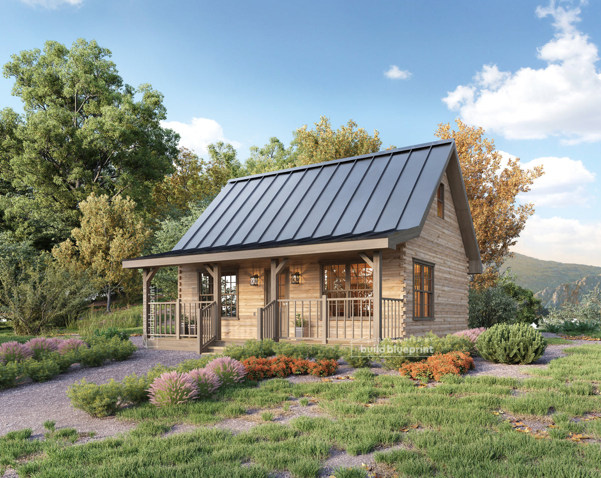

Most first-time builders purchase a plan set before they know how to read one. That's not a problem — architectural drawings aren't difficult to interpret once someone walks you through the conventions. But walking into a permit counter or a contractor meeting without understanding your own plans costs you credibility and opens the door to costly miscommunications.
This guide covers every sheet in a standard cabin plan set, what each one shows, and what to look for on each page before your build starts.
The Cover Sheet
The cover sheet is the table of contents for your plan set. It lists every sheet included in the package, the applicable building codes the design was drawn to, general construction notes, and the designer's contact information. Building departments use the cover sheet to verify the plan set is complete before accepting it for review.
Read the general notes section carefully. This is where the designer records assumptions: foundation type the plans were designed for, wall assembly (2x4 or 2x6 studs), insulation requirements, and any site conditions the builder needs to verify. Notes here aren't suggestions — they define the design intent behind every other sheet in the set.
Floor Plans: The Sheet You'll Use Most
A floor plan is a horizontal cut through the building at roughly window height, looking down. It shows the layout of every room on that level — walls, doors, windows, stairs, and built-in elements like kitchen cabinets and bathroom fixtures.
Walls are shown as parallel lines. Thicker wall assemblies (exterior walls, typically 2x6 construction) appear wider than interior partitions (typically 2x4). Hatching or fill patterns inside the wall lines indicate the wall type.
Doors are shown as a gap in the wall with an arc indicating the swing direction. The arc tells you which side the door is hinged on and how far it swings — critical when furniture planning and when checking that doors don't conflict with each other when open.
Windows appear as three parallel lines crossing the wall. The center line represents the glass; the outer lines represent the frame.
Dimensions run along the edges of the floor plan and between key elements. There are two types: overall dimensions (the total footprint of the building) and interior dimensions (room sizes, wall-to-wall). Verify that the room dimensions listed match what you expect. A bedroom labeled as 10' x 12' is a real bedroom. A bedroom that dimensions out to 8' x 9' is a tight squeeze.
Room labels identify the function of each space. Cross-reference room labels against the elevation drawings and section drawings to understand ceiling height and roofline over each space — the floor plan alone doesn't tell you how tall a room is.
Reading Scale
Architectural drawings are drawn to scale — typically 1/4" = 1'-0" for floor plans, meaning every quarter inch on the paper represents one foot of actual construction. This scale is printed on each sheet. When plans are printed at the correct sheet size (typically 24" x 36" architectural D-size sheets), a standard architect's scale ruler lets you measure any dimension directly off the drawing.
If you're viewing plans on a screen or printed at a reduced size, the printed scale is no longer accurate — rely only on the labeled dimensions, not on measuring the drawing directly. This is a common source of confusion for first-time plan buyers.
Exterior Elevations
Elevations are straight-on exterior views of all four sides of the building — typically labeled Front, Rear, Left, and Right. They show the roofline and pitch, window and door placement and sizes, siding material, and finished grade line (the ground level around the building).
What elevations tell you that floor plans don't: wall height, roof overhang, and how the exterior will actually look. The finished grade line is important — it shows how much of the foundation will be exposed above ground, which affects both appearance and water management at the foundation perimeter.
Cross-reference the elevation with the floor plan to verify that every window and door shown on the floor plan appears on the corresponding elevation at the right location. Discrepancies between sheets are rare in professionally drawn plans but worth catching before your framing crew does.
Building Sections
A building section is a vertical cut through the structure, showing how it's assembled from foundation to ridgeline. Sections are the most technically dense drawings in the set and the ones that most directly govern construction.
What to look for in a section drawing:
- Floor-to-ceiling height: Listed on the section, not the floor plan. Standard cabin ceiling heights run 8'–9' on the main floor. Vaulted or cathedral sections will show the full rake from wall plate to ridge.
- Roof pitch: Shown as a slope indicator (e.g., 8:12 means 8 inches of rise for every 12 inches of horizontal run). Steeper pitches create more loft headroom and shed snow more effectively. Flatter pitches reduce material cost and framing complexity.
- Wall assembly: The section shows the layers of the wall — sheathing, framing, insulation cavity, interior finish. This determines your insulation R-value and wall thickness.
- Structural members: Ridge beam size, rafter size, floor joist size, and bearing locations are called out in the section. Your framing crew uses this to order lumber.
Foundation Plan
The foundation plan shows the layout, dimensions, and specifications of the structural base. Depending on foundation type — slab, crawl space, or piers — it will show footing locations and sizes, reinforcement (rebar) placement, anchor bolt spacing, and any grade beam details.
Your concrete contractor works from this sheet. Before your pour, verify that the foundation plan matches the building footprint shown on the floor plan — the dimensions must align exactly. Any discrepancy needs to be resolved before concrete is placed, not after.
For a detailed look at foundation types and which is right for your site: Concrete Slab vs. Pier Foundation: Which Is Right for Your Cabin?
Electrical Plan
The electrical plan overlays the floor plan with symbols showing outlet locations, switch placements, light fixture locations, panel location, and circuit notes. Electrical symbols are standardized — a circle with lines is a ceiling fixture; a half-circle on the wall is a wall sconce; a rectangle with slots is a duplex outlet.
Your electrician uses this plan to price the rough-in and to pull the electrical permit. Building departments typically require an electrical plan as part of the main permit submission. Review the outlet layout before your build starts — repositioning an outlet during rough-in is a five-minute change; repositioning it after drywall is a patch job.
Common Abbreviations You'll See
- TYP — Typical (applies to all similar conditions)
- SIM — Similar (same detail applies at a similar location)
- CLG HT — Ceiling Height
- HDR — Header (structural beam above a door or window opening)
- OH — Overhead
- CL or ℄ — Centerline
- FF or FFL — Finished Floor (Level)
- TOS — Top of Slab or Top of Sheathing
- W/ — With
- R/O — Rough Opening (the framed opening size for a window or door, which is larger than the unit itself)
How to Review a Plan Set Before You Buy
When evaluating any plan set, work through these checks before purchasing:
- Verify the overall footprint dimensions match the listed size.
- Confirm bedroom dimensions are livable — not just labeled.
- Check that door swings don't conflict with each other or with appliances.
- Locate the electrical panel on the floor plan and verify it's in a code-compliant location (not in a bedroom or bathroom).
- Confirm the section drawing shows an adequate ceiling height over all occupied spaces.
- Verify the foundation plan matches the footprint on the floor plan.
Build Blueprint plan sets include all required sheets — floor plans, elevations, sections, foundation plan, and electrical plan — drawn to standard construction methods and formatted for permit submission. For a full breakdown of what's in a complete set: What's Included in a Set of Cabin Plans?
Commonly reviewed plans:
- 20' x 26' Adirondack permit-ready set — 2 bed, 1 bath, 650 SF, loft, most popular plan
- 24' x 34' Large Adirondack permit-ready set — 3 bed, 2 bath, 816 SF
- 24' x 36' Nordic A-Frame permit-ready set — 3 bed, 2 bath, 1,152 SF, A-frame design
- 32' x 32' Alpine permit-ready set — 3 bed, 2 bath, 1,024 SF, open plan with covered porch
The Bottom Line
Architectural drawings follow consistent conventions that take less than an hour to learn. The payoff is significant: you can evaluate a plan set before purchasing, have an informed conversation with your contractor, and catch discrepancies before they become field problems. Start with the cover sheet, work through the floor plans with dimensions in hand, then cross-reference against the elevations and sections. By the time you've walked through all five or six sheets, you'll have a complete picture of what you're building — and the confidence to move forward.